Sequence Diagram - Reading Guide

|
Project:
|
Sequence Diagram - Reading Guide : Interaction diagram
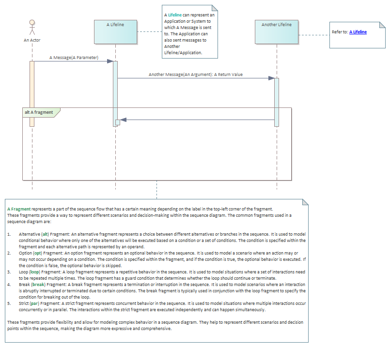
A <font color="#2e8b57"><b>Sequence Diagram</b></font> is a type of diagram used in Unified Modeling Language (UML) to visualize the interactions and ordering of messages between objects or components within a system or software application. It provides a time-ordered representation of the interactions, showing the flow of messages and the sequence of events that occur.<br/><br/><b><i>Purpose of a Sequence Diagram</i></b><br/>Sequence diagrams are commonly used for the following purposes:<br/><ol>
<li>Modeling Behavior: Sequence diagrams help model and understand the behavior of a system by showing the interactions between objects or components. They illustrate how objects collaborate to perform a particular function or fulfill a use case.</li><li>Communication: Sequence diagrams serve as a communication tool between stakeholders, developers, and designers. They provide a visual representation of how different parts of a system interact with each other, making it easier to discuss and understand the system's behavior.</li><li>Identifying Issues: Sequence diagrams can help identify issues or bottlenecks in the system's design or implementation. By visualizing the sequence of messages and interactions, it becomes easier to identify potential problems or areas for improvement.</li><li>Documentation: Sequence diagrams can be used as documentation to capture and record the design and behavior of a system. They provide a clear and concise representation of the system's interactions, making it easier to understand and maintain the system in the future.</li></ol> <br/><b><i>Components of a Sequence Diagram</i></b><br/>A sequence diagram consists of the following components:<br/><ol> <li>Lifelines: Lifelines represent the objects or components involved in the interaction. They are depicted as vertical lines and typically have the name of the object or component written on top.</li><li>Messages: Messages represent the communication or interactions between lifelines. They show the flow of information or requests being sent from one lifeline to another. Messages can be synchronous or asynchronous, and can have parameters or return values.</li><li>Activation Boxes: Activation boxes represent the time period during which an object is actively processing a message. They show when an object is "activated" or engaged in processing a message and when it is idle or not actively processing.</li><li>Return Messages: Return messages are used to represent the response or return value of a message. They show the flow of information back to the calling object.</li><li>Conditions and Loops: Sequence diagrams can also include conditions and loops to represent decision-making or iteration within the system's behavior. These elements provide more flexibility and detail in modeling complex interactions.</li></ol> <br/><font color="#2e8b57"><b><i>In DCSA Sequence Diagrams are more tuned to the standard and are used to document API usage.</i></b></font><br/> |


